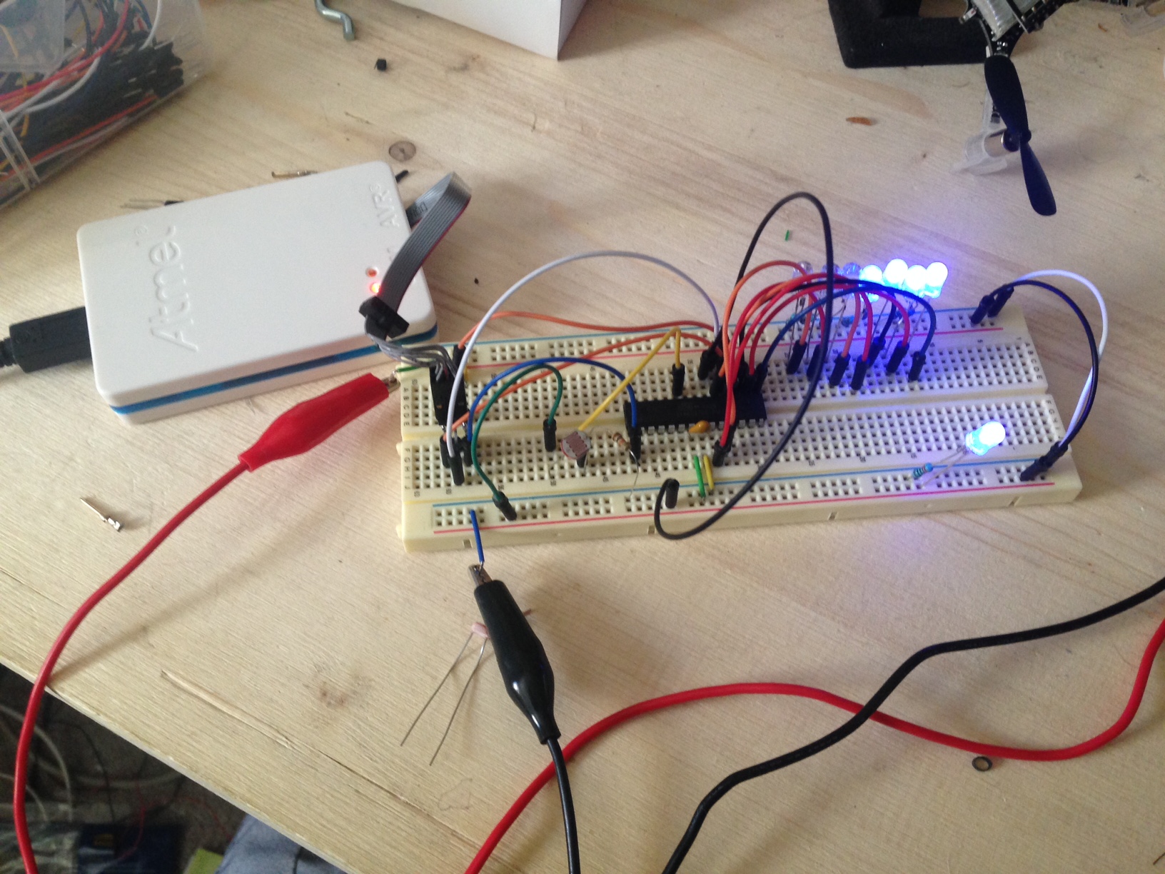
For input devices I decided to create a fun device using a light sensor. My circuit as seen above uses the light sensor/resistor to measure the amount of light and displays a general reading using a bargraph of LEDs. I would recommend checking out the microcontroller datasheet like I talked about earlier to find the operating voltage, clock, memory capacity, and pinouts for your microcontroller. It is also a good idea to keep a picture of the pinouts for the microcontroller you are using. |
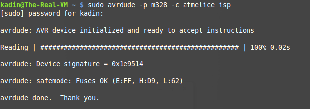
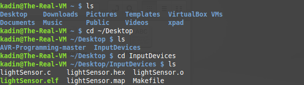
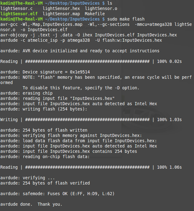
As before, to program the processor in Linux simply, check your programmer is communicating with the chip, navigate to the location of your software and make file, and finally flash the software to the processor. |
This is the result. Above is the product of my input devices circuit and software. As you can see the bargraph changes as the light changes as intended. You can get the code for this here. And the makefile here. |
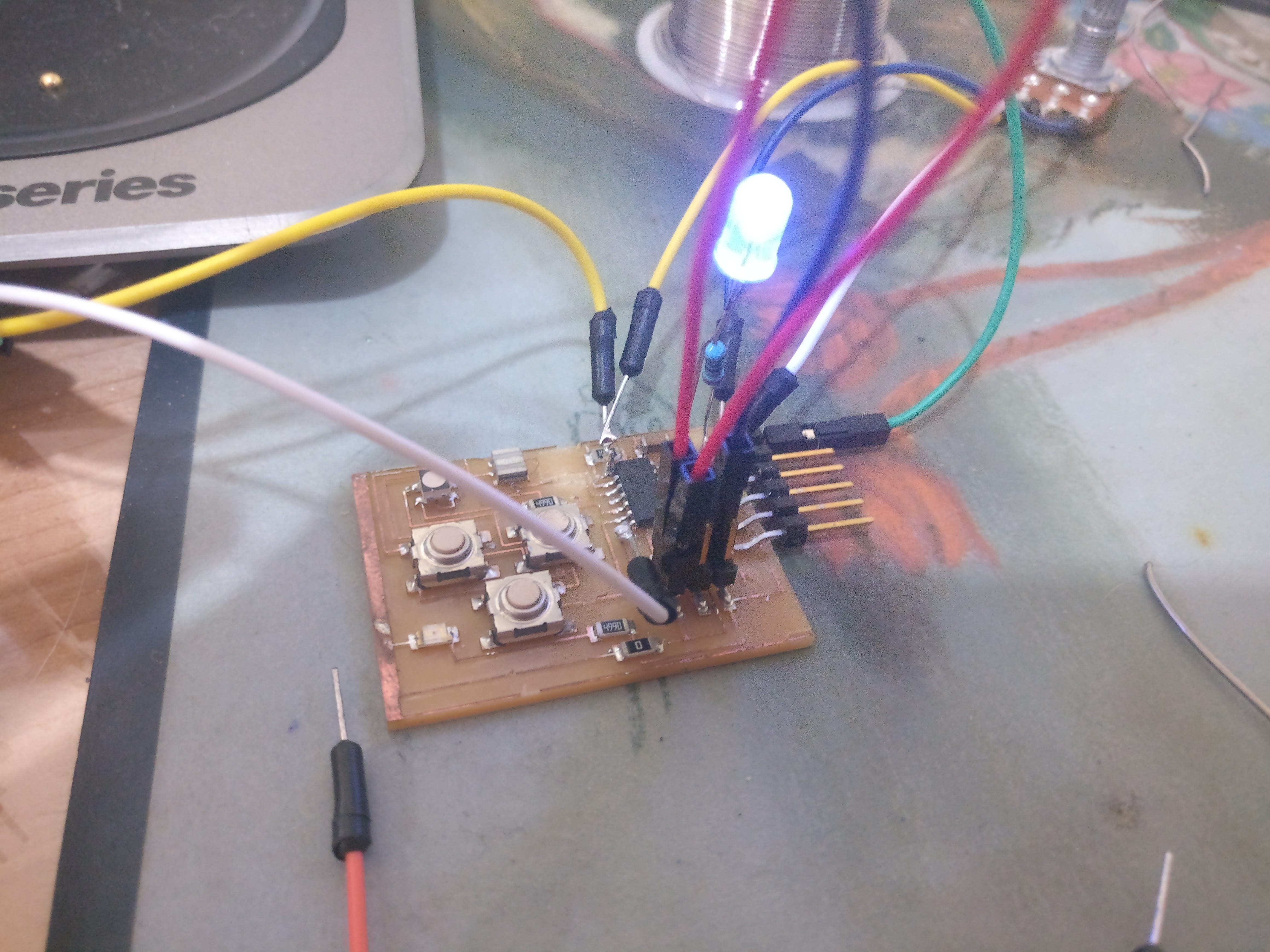
For my second project of the week I will be using my milled PCB board from my electronics design week. At the time of doing this project I do not have access to a Fab Lab so I will be unable to make a new PCB board. For that reason I will being turning my week 6 PCB into a bit of a Frankenstien monster as seen above. |

As for the software side of this week, I used Arduino IDE. I used this tutorial to set up Arduino IDE with my Attiny44A board, as recommended by Ki(A fellow member of the CITC Fab Lab). |

Once I followed the steps in the link in the previous paragraph I deviated from its path. I decided to program with a USBasp programmer for this project instead of a USBTiny, Atmel ICE, or Fab ISP, all of which I have used before. The only real difference I found was the USBasp has a 10 pin rather than a 6 pin interface. |
The program I used is relatively simple. All I did was take the blink example from Arduino IDE and make some tweaks to make delay timings between flashes based on an anolog read rather than a pre set value. I also adjusted the pins to make the sketch compatible with my Attiny44A board. |
Once completed the LED on my Fab board blinked on and off based on the value/position of the potentiometer as seen above. Although it was messy this second project highlighted the same principles as the first and did it on a milled board that I made in the Fab Lab as required by the grading rubric. |
Lastly, I removed the soldered on LED and ran the same program using the onboard LED. Unfortunately the VCC pin on the Attiny fell off so I had to hold the 5v wire to the chip which makes it hard to see what is going on, but here it is anyway. |